

How to accurately measure leakage current - Interference from power supply ripple
Release time:
2023-12-20 08:59
Source:
Xinhua
In the previous lesson of "Testing Technology Science Popularization Class", we learned that the measured current measured by the MLCC tester actually includes the five parts shown in the figure below: Imeasured current = I1 + I2 + I3 + I4 + I0
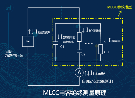
In this chapter, we will focus on analyzing the I2 component, the impact of different levels of power supply ripple on I2, thereby understanding the importance of the power supply, and how to evaluate the size of the power supply ripple to meet the needs of the MLCC tester.
So, how to evaluate the ripple of the MLCC test system power supply?
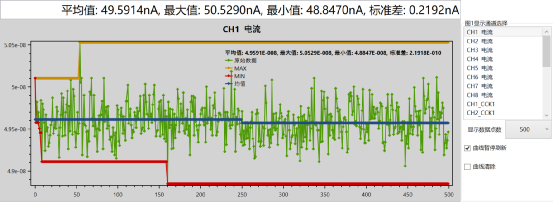 Figure: Self-developed power supply + self-developed instrument
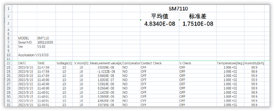
Figure: Imported Yokogawa: SM7110 high-resistance meter + automatic Yokogawa test software system
Therefore, although the 34uV ripple is considered relatively low, the impact of this level of ripple reaches 17nA, which is too high a proportion for the actual leakage current, seriously affecting the accuracy of high-speed measurement in production, and may lead to unreliable measurement data and misjudgment of measurement results.
Our instrument's power supply ripple is far less than 1uV, and the interference current caused is only 0.2192nA, which greatly reduces the interference caused by the power supply ripple of the power supply system and ensures the primary condition for accurate measurement—an ultra-low ripple precision voltage source.
Contact Us
Add:1st floor, Building 1,Bojay building, 10 Futian Road, Xiangzhou District, Zhuhai, Guangdong, China Fax:+86 - 756 - 8911908


Mobile Website